

The following figure shows the correct wiring for a 10Base-T crossover cable (assuming you're using RJ-45 connectors).
This cable can be used to connect two computers together without a hub, or to connect two hubs together (without using an uplink port). If you're connecting two hubs together and one of them has an uplink port, use a straight cable (rather than the crossover) to connect the uplink port of one hub to one of the (non-uplink) ports of the other hub.
A bit of technical background: Most computer and workstation network adapter cards have interface ports referred to as MDI ports (RJ-45 pin assignments shown on the left side of the above drawing). "Uplink" ports on hubs have the same pin assignments. Most normal ports on hubs have MDI-X ports, which use pins 1 and 2 for receive, and pins 3 and 6 for transmit. A straight cable (one that connects pin 1 to pin 1, pin 2 to pin 2, etc.) can be used to connect an MDI port (a computer) to and MDI-X port (a normal port on a hub). Obviously, to connect two MDI ports together, it is necessary to connect pin 1 to pin 3, pin 2 to pin 6, and so forth.
The RJ-45 connector is commonly used for network cabling and for telephony applications. It's also used for serial connections in special cases. Here's a look at it:
![]()
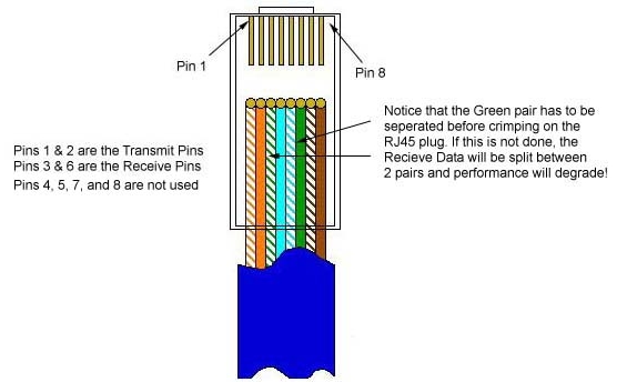
Also, please note that it is very important that a single pair be used for pins 3 and 6. If one conductor from one pair is used for pin 3 and a conductor from another pair is used for pin 6, performance will degrade. See the following figure.
To learn more about Ethernet, check out Charles Spurgeon's Ethernet Reference.
![]()
The following chart shows the pinout for RJ-45 connectors used on certain RocketPort serial interface cards (manufactured by Comtrol).
| Pin | Name/Description |
|---|---|
| 1 | Request To Send |
| 2 | Data Terminal Ready |
| 3 | Ground |
| 4 | Transmit Data |
| 5 | Receive Data |
| 6 | Data Carrier Detect |
| 7 | Data Set Ready |
| 8 | Clear To Send |
![]()
Here's an ISDN BRI U port pinout for a Cisco 750 series router:
| Pin | Function |
|---|---|
| 1 | Not used |
| 2 | Not used |
| 3 | Not used |
| 4 | U interface network connection (tip) |
| 5 | U interface network connection (ring) |
| 6 | Not used |
| 7 | Power (pass-through to S connector) |
| 8 | Ground (pass-through to S connector) |
The following chart shows the pinout for RJ-45 connectors used on certain ISDN S/T interfaces. For more info, see ANSI T1.605.
RJ-45 wiring for Ethernet (T568B standard)
| Pin | Color | Name/Description |
|---|---|---|
| 1 | White/Orange | N/A |
| 2 | Orange | N/A |
| 3 | White/Green | Receive+ |
| 4 | Blue | Transmit + |
| 5 | White/Blue | Transmit - |
| 6 | Green | Receive - |
| 7 | White/Brown | -48VDC (optional) |
| 8 | Brown | -48VDC Return (optional) |